Download: AnkerMake M5 3D Printing Machine [pdf] User Guide
Buy One: AnkerMake M5 3D Printing Machine
Product Profile
Introduction
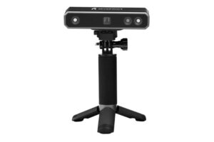
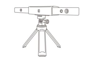
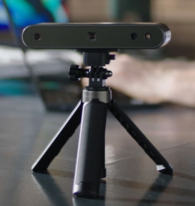
The newly developed POP 2 3D scanner has gathered functions of a handheld 3D scanner and a desktop 3D scanner, bringing together the company’s latest scientific research results. It adopts self-developed 3D camera hardware technology and high-speed intelligent chip, which contributes to a higher performance and directly outputs accurate depth information of an object.
The core hardware of POP 2 applies the principle of binocular & Micro-structured light, and with the help of the proprietary micro projecting chip, POP 2 ensures fast acquiring high-accuracy (up to 0.05mm) 3D point cloud data. And it supports texture scanning to directly generate vivid 3D models for color 3D printing. As of intelligent algorithms, POP 2’s built-in high-performance 3D calculation chip can effectively ensure smoothly scanning without stalling even if it is used with an ordinary computer.
Specifications
| Product Name | 3D Scanner |
| Product Model | POP 2 |
| Technology | Dual camera infrared structured light |
| CPU | Dual core ARM Cortex-A7 |
| Single- frame Precision | 0.05 mm |
| Single capture range | 210mm x 130mm |
| Working distance | 150 mm ~ 400 mm |
| Minimum scan volume | 20×20×20 (mm) |
| Scan speed | Up to 10 fps |
| Light source | 1 class infrared Laser |
| Alignment | Feature, marker and color |
| Press button | Yes |
| Output format | PLY, OBJ, STL |
| Texture scan | Yes |
|
Special object scanning |
For the transparent and highly reflective objects, please use scanning spray powder. |
| Outdoor scanning | The cover is needed to avoid interference of intense light. |
| Scanner weight | 195g |
| Dimensions | 154.6 ×38.2 × 25.6 (mm) |
| Printable data output | Able to export 3D model directly to 3D printing |
| Required computer configurations | Windows 8 / 10 / 11 (64-bit), Android, iOS, MAC |
| Wi-Fi | 5 GHz |
|
Connection Type |
Micro-B – Type-A USB |
|
Note |
*The aforesaid accuracy is acquired in standard lab environment, which might vary subject to actual operating environment.
* Windows 7 is not supported. |
Packing List
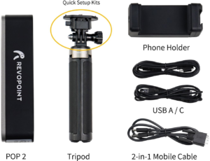
POP 2 Standard
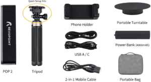
POP 2 Premium
Hardware Connection
Laptop Connection
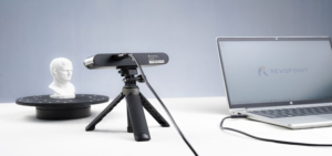
Make sure the POP 2 scanner is connected to a USB 3.0 or above port, because USB 2.0 will not supply sufficient operating current. An indicator of this is repeated power resets and lost connections.
*The display screen resolution recommended is 1920×1080.
Wireless Connection to a Smartphone
For Wi-Fi settings, Host mode is default. In this mode, a smartphone could connect to the Wi-Fi provided by the POP 2 3D scanner.
The default SSID is: POP2-REVO-XXXXXXXX The default Password is: Revopoint3d
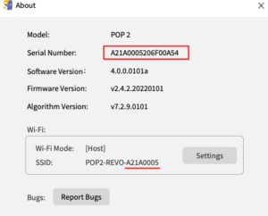

For example: If the Serial Number of one POP 2 3D scanner is: A21A0005206F00A54. The Default SSID: POP2-REVO-A21A0005
The Default Password: Revopoint3d
How to revise the SSID and Password:
- ConnectPOP 2 3D scanner to a PC via USB cable and Open the Revo Scan;
- ClickAbout –àSettings;
- Detetethe default SSID and Password to enter the one as you
For a SSID, enter 1-32 characters;
For a Password, enter 8-32 numbers, English letters or punctuation marks in any combination( no space characters).
Indicator Legend
Blue Light: Starting
Green Light: Working Correctly
Do not look at the front light of the projector closely for a long time! Refer to Standards for Class 1 Lasers for details.
Software Installation
System Requirements
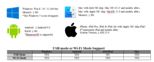
Install Software
Three softwares are provided: Revo Scan, Revo Studio and Revo Calibration.
The Revo Scan is a scan software that assists in scanning objects and obtaining 3D models; the Revo Studio is a post- process software for postprocessing the scanned 3D models; the Revo Calibration is a Calibration Software that adjusts the parameters of POP 2 for ensuring good results.
Download the Revo softwares at our website:revopoint3d.com/download-2/
i� The post-process software- Revo Studio and calibration software– Revo Calibration will be introduced successively, and the related instructions will be available then. Revo Studio and Revo Calibration user manuals are not included in this one and will be brought to you separately.
Revo Scan- UI Introduction
In this section, we will introduce the user interface.
1. Main Menu Panel
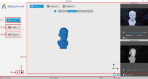
① Scan: Access the Preview, New Scan and Model List functions. The ‘Preview’ command displays the POP/POP 2’s scanning as currently configured. The ‘New Scan’ command brings up the configuration popup (see Section 2 on page 9). The Model List command lists the library of stored scans with the option to perform various operations on individual files or in Batch mode.
② Guide: Present the User Manual, Quick Start Guide and Scanning Tips, plus a link to the latest software.
③ Support: Provide links to the Online Help, FAQ and Forum, plus a link for Feedback. The Online Help allows our Customer Service Team to support Users in a timely manner, and Feedback is linked to the Revopoint email support@revopoint3d.com , to submit ideas or any other feedback about our products.
④ System Settings: Specify language and data storage location, plus the hardware accelerated rendering switch for the
computer’s GPU.
⑤ About: Display the version information for the POP/POP 2 and Revo Scan, confirm or configure Wi-Fi and report bugs.
⑥ Status Bar: Display the POP/POP 2’s connection status, connection mode and scan readiness.
⑦ Display the content for the operation specified in ①, ② or ③.
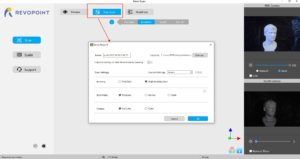
2. New Scan
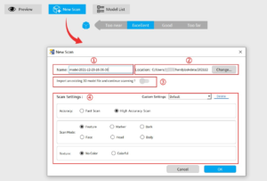
① Name: Display the default name of the model to be created. Rename it as needed.
② Location: Display the file folder of the model to be saved. Change as needed.
③ Import an external model: Turn on and click “Browse” to import a 3D model in .PLY, .OBJ or .STL formats
into Revo Scan to continue scanning and capture more details.
④ Scanning Settings:
Accuracy: Fast Scan and High-Accuracy Scan
Fast Scan: Faster scanning, but the accuracy in this mode is relatively lower than with High-Accuracy scans.
High Accuracy Scan: Added to meet users’ needs for higher-precision data capturing. In High Accuracy mode, the processing time for point cloud fusion/mesh/texture operations will be relatively longer.
Scan Mode: Include Features, Markers, Face, Head, Body and Dark
Feature: Designed to scan objects with unique shapes such as sculptures and easily-identifiable features.
Marker: Designed to scan objects that have large, smooth areas or regularly-repeating features that could fool the POP/POP 2’s internal pattern recognition capabilities. Flat planes like a board or symmetrical objects like balls or bowls are usually suitable to scan with this mode. Place tracking markers irregularly on or around the objects. Remember to distribute the markers so they do not have repeating patterns because the scanner determines the relative location of each frame of point cloud data by identifying the unique patterns formed by the markers. Plan ahead to keep six or more markers (the red dots in the display) in view for each frame during the scanning process.
Dark: Designed to scan objects with darker surfaces, such as black or dark gray clothes, black boxes, etc. However, not all dark objects can be successfully scanned. One example would be black leather shoes because leather
absorbs light (or they are so shiny that they reflect too much light). The exposure and gain are set accordingly (no Automatic exposure adjustment).
Face: Designed to scan the human face. The exposure and gain are set according to typical skin reflectivity (no Automatic exposure adjustment).
Head: Designed to scan hair (including dark hair) along with the face.
Body: Designed to scan a human body or larger objects from a greater distance than is used for the other modes. The exposure and gain are set accordingly (no Automatic exposure adjustment)
Texture: No Color and Colorful
No color: The scanned model has no color information; only the shape information is captured.
Colorful: The object to be scanned has both color and shape information in the scanned 3D model (Revo Scan can only export color objects in the .PLY & .OBJ file formats).
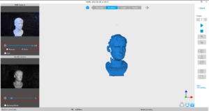
3. Scanning UI
After clicking “OK” on the New Scan popup, the real scan UI shows:
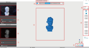
① Name: Display the Name specified in the New Scan configuration popup.
② RGB Camera: Display the image captured by the RGB Texture camera.
Note: The Grid option aids in positioning the object to be scanned so that the cameras can see it.
③ Depth Camera: Display the 3D point cloud data that can be captured with the current Exposure setting.
Note: The Clip Plane option is designed to remove unwanted planes in the scene such as the turntable, desktop or floor. Objects with significant flat areas can fool this tool, so it may be necessary to untick this option.
④ 3D Model
Preview Window: Display the 3D model data that will be captured when scanning starts or all of the data that has been captured after scanning has started. The view of the model may be dragged or zoomed in the 3D Model preview area by the mouse (Left Mouse Button: Rotate the model; Wheel: Zoom in/out).
⑤ Tool bar:
Icon : Reset the view of the model to the default position in the 3D Model Preview Area. This is determined by the first scanned frames of the object.
Icon : Hide or show the background in the 3D Model Preview window.
Icon : Switch between Color/No-color point cloud data.
Note: If No Color was specified in the New Scan configuration popup, the icon is displayed as locked ( ).
⑥ Scanning
Distance: Too near, Excellent, Good, Too Far. ~
Placing the POP/POP 2 or the object to be scanned so that it is in the Excellent zone will have the best balance of resolution and tracking. Adjust the optimal distance according to the prompt. Higher-resolution scans can be made in the “Too near” range, but it is more likely that tracking will be lost.
⑦ Exposure and
Gain adjustment: Brightness and Gain (the sun icon ) can be manually adjusted for best results (the areas not displayed in red will return point cloud data while scanning). Some Scan Modes allow for Automatic adjustment to find the best setting, but remember to switch to Manual before scanning to prevent exposure variations that interfere with data capture.
⑧ Timer: Count down from an arbitrary number (default is 3 seconds) to indicate the time remaining
before scanning.
⑨ Function Buttons:
Icon / : Start or pause scanning.
Icon : Stop the current scanning project. A popup will allow choosing between completing the scan (fusing the Point Cloud) or deleting the entire project to start over from Step 1.
Icon and : Undo or Redo several scanned frames of the model at a time.
Mesh : Maps the scanned 3D point cloud data into planes or triangles.
If “No Color” was selected when the Scan Mode was defined, the model only consists of point cloud and mesh information.
If the “Color” option was selected, then the model will also contain the color information of each point.
Texture : Match pixels of the picture on the mesh model to improve the texture and color resolution.
Export : Export the completed 3D model.
i� The text icon” Save The Settings” is used to keep the Scan Settings in New Scan and Parameters in Scanning UI.
4. Model List
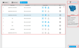
① Model Viewing Area: Lists all models scanned, creation timestamps and status.
The icon sequence means that the model has completed scanning.
The icon sequence means that the model has been scanned and its point cloud has been fused. The icon sequence means that the model has been scanned, fused and meshed.
The icon allows users to open, rename, delete and export the model.
② Import Project: Import a 3D model into the model list.
③ Thumbnail preview: Select a model in the ① Model Viewing Area and its thumbnail displays in this area.
④ Details: Display the model’s scan information.
⑤ Batch Processing: Select more than one model and process (fuse, mesh and texture) them in one go.
Revo Scan – Workflow
Double Click to open Revo Scan—> Confirm “Device is connected” (displays after several seconds) —> Click New Scan to select Accuracy, Scan Mode and Texture —> Confirm distance to be “Excellent” —> Adjust the brightness in RGB camera and Depth Camera (Auto first, if available, then Manual) —> Start/Pause Scanning —> Stop to Complete/Restart Scanning
—> Fuse Point Cloud —> Mesh —> Texture (only available for Colorful scans) —> Export the 3D model
Confirm “Device is connected”
After opening Revo Scan, confirm the device connection status:
If the device is connected successfully, the left end of the status bar displays: Device is connected. Otherwise, please check the connection. This happens typically 8-10 seconds after the POP/POP 2’s status LED on the rear panel turns blue.
Click New Scan to select Accuracy, Scan Mode and Texture
Once connected successfully, the device is ready to scan. Configure the desired operational characteristics as described in Section 2. New Scan (see p. 9-10) of the UI Introduction.
Confirm distance to be “Excellent”
After specifying the Accuracy, Scan Mode and Texture options, press “OK” to enter the scanning page. The top area of the 3D Model Preview window shows the distance. Position the POP 2 scanner or the object to confirm an “Excellent” distance and keep it during scanning. Higher-resolution scans are possible in the “Too near” range, but tracking is more likely to be lost.

Adjust the brightness in the RGB Camera and Depth Camera
Adjust the Sun Icon on both of the smaller displays (for Android and iPhone smartphones, click on the Gear icon in the upper right of each small window to make the controls visible). If available, try Auto first, but switch back to Manual before capturing data to prevent lockups.
Note:
| Underexposure ( in Blue) | Perfect | Overexposure ( in Red) |
Start or Pause Scanning
Click / to Start/Pause scan. The number above the Start button is the countdown before scanning starts.
During scanning, please make sure the point cloud in the lower-left window is adequate and the distance remains “Excellent”. Move the scanner slowly and deliberately during scanning while keeping a relatively fixed distance. Already- scanned sections of the model are displayed in blue. Unless there are holes in the scan, there is no advantage to continuing to scan a blue area (and it will waste memory and processing time).
Complete/Restart Scanning
Click and the “Complete” button in the popup to fuse the point cloud data, or press the “Restart” button to delete the data and return to the Preview section (p. 8).
After clicking Stop, it is possible to resume scanning (say, after repositioning either the POP/POP 2 or the object being scanned). If this is desired, then be sure to move the slider switch for “Fuse point cloud immediately?” to the right before clicking “Complete”. The scan data will be fused into a point cloud immediately. After this, meshing the point cloud data or resume scanning are available.
Inactive button in the Stop’s popup (so that Fusing is a manual operation, allowing changes in the preset):
After clicking “Complete”, the next step is to fuse the point cloud data, as shown below:
Click the drop-down arrow to display the Fuse setting. The smaller the point pitch, the better the result. But the point pitch of the fused object cannot be smaller than the point pitch of the original scan. The pitch point is at a minimum of 0.1 mm for the POP 2. Smaller pitch points result in higher resolution, but also more processing time.
Mesh
Click to start converting the scanned point cloud data into a mesh.
In the drop-down box, settings for Mesh Quality and Denoise are provided:
With higher Mesh Quality settings, more details are captured in the resulting model, at the expense of longer processing times. The higher the Denoise setting, the smoother the result. Depending on the object, high levels of noise reduction may result in lost detail. The results of the Fill Hole switch may be undesirable if the holes are too large.
Texture
The Texture function only applies to scans made with the “Colorful” option selected (see New Scan options on p. 9). Click to apply texture to the model.
Export
Click to export the 3D model.
Select a file name and. a file format (.PLY, .OBJ & .STL, are supported).
File Naming Conventions
Save the 3D model as a .PLY file NAME.ply (Point Cloud) NAME_mesh.ply (Mesh no color) NAME_mesh_tex.ply (Mesh with color)
NAME_mesh_tex.jpg (Texture color image)
Save the 3D model (no Color/Texture) as an .STL file:
NAME.ply (Point Cloud) *
NAME_mesh.stl (Mesh no color) **
*Point clouds are saved in the PLY file format, because STL does not support point clouds
**Color models are not saved in the STL file format
Save the 3D model (with Color/Texture) as an .STL file:
Revo Scan does not support color scans in the .STL file format, so they are saved as .PLY.
Save the 3D model as an .OBJ file:
NAME.obj (Point Cloud) NAME_mesh.obj (Mesh no color) NAME_mesh_tex.obj (Mesh with color) NAME_mesh_tex.mtl
NAME_mesh_tex.jpg (Texture color image)
NOTE:
NAME_mesh_tex.obj, NAME_mesh_tex.mtl & NAME_mesh_tex.jpg are the three components of a color 3D model in the OBJ file format.
Operation Tips
Lose Track
If the 3D Model Preview window displays a “Lose track” notice during scanning, please re-target the POP 2 3D scanner to a previously-scanned area (blue) and keep still for several seconds so that the POP 2 can re-acquire tracking. When the red portion of the display changes to green, scanning can resume.
Too Few Points
If the “Few Point Amount” prompts appear, check whether the distance between POP 2 and the object is too close or too far and adjust the distance between the POP 2 and the object so that the distance indicator highlights “Excellent” before scanning is continued.
Detect Plane
This prompt appears when a plane or object with too few features is scanned and the POP 2 cannot properly relate the frame’s point cloud to the other frames. If no usable data has been scanned, the best course of action is to Stop scanning, select Restart to clear out the useless data, then start a new project, this time selecting Marker mode after attaching markers to the scanning surface or the surrounding area to solve this problem. If a significant amount of scan data has been acquired, then pause the scan, use Undo as necessary to eliminate the chaff, then Stop, Complete and Export the scan data before continuing in Marker mode.
Undo/Redo scan
If a point cloud alignment error appears in scanning, you can click “Undo”repeatedly to the point that the 3D model is clean enough to continue or save. Otherwise, if the point cloud is deleted more frames mistakely, you can click “Redo”
to find them.
Continue Scan
·Continue Scanning After Point Cloud Fusing:
It is possible to continue scanning an object after the point cloud data has been fused. This can be necessary if the scanning controller (a computer or smartphone) runs out of RAM to capture more frames or if holes in the scan data are discovered. This process can be repeated as needed until the model meets your requirements.
·Import a model file to scan over holes:
3D model files with defects can be fixed by continuing the scanning process:
First, move the slider switch for “Import an existing 3D model file and continue scanning?” to the right. Second, click Browse to pick the 3D model.
Batch Processing
“Batch processing” improves workflow by automatically applying the same settings for each operation to a selected group of scanned models.
Fast speed: the model processing will be completed as quickly as possible;
High accuracy: while the model processing, the accuracy has priority over other elements.
Custom: Users can adjust the parameters of point distance, mesh quality and denoise to get the models needed.
Keyboard Shortcuts
Press the “Space Bar” on your computer keyboard to toggle between Start and Pause.


